Quantcast
Channel: AE1S Science and Engineering Blog
Viewing all 72 articles
Browse latest View live

N2PK VNA Transverter options

$
0
0
The N2PK VNA frequency range can be extended by using transverters. While the N2PK VNA covers the entire 0.05 to 60 MHz, additional frequencies are covered only on specific bands. Paul, N2PK and Ivan, VE3IVM developed two transvertersin order to cover the 2m and 70 cm amateur bands.

Both transverters share exactly the same design and PCB with only a few differences in the BOM - the frequency of the Local Oscillator (180 MHz for the 2m version and 400 MHz for 70cm) and the the components of the Band Pass Filter (different set of components for each filter, changing their frequency range).
I started with the 2m transverter kit from Ivan, VE3IVM. It was an easy and pleasant build - Ivan provided a partial kit - PCB, LO, BPF coils, balun transformer for the bridge, both mixers and a power splitter- the rest of the BOM is from Digikey.
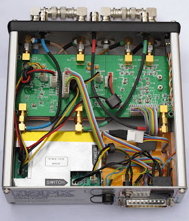
The top side of the PCB. The 4 coils of the BPF are shielded, each in its own compartment. It is important that they are centered and lifted from the ground plane in order to increase the Q and minimize losses. The other components are the LO, both mixers, RA SMA connectors and the voltage regulators - +6V and +5V. The most time consuming task here is to make and install the shield for the BPF coils - a certain level of precision is required while fabricating the RF shield as the tolerances are not very large. The top cover is soldered during the finalization stage. I used tin-plated brass sheet to make all RF shields - this material is very easy to form and solder.

Most of the components are installed on the bottom side. Again, a lot of attention is required when building the BPF and the bottom shield for it. After adjusting the BPF, the bottom shield is installed and the filter is checked and re-aligned again as the shield might de-tune it a little. The attenuators are pretty small and should be soldered very carefully. Same thing goes for the 100 Ohm 0604 bridge resistors. The two amplifiers should be soldered carefully to avoid over-heating. Ivan provides specific instructions for installing the variable caps - no flux (or very minimal) should be used and the board must be washed with alcohol or flux remover to avoid mechanical damage to the trimmer capacitors. This picture shows an incomplete and bypassed Low-Pass filter on the low-side output. The jumper is removed and the rest of the components are installed during the finalization stage and after final alignment of the BPF.

This is a plot of the BPF frequency response from the initial alignment of the filter. I was aiming at 143 MHz - 153 MHz range. The BPF filter design allows for almost 10 MHz bandwidth in the 2m band and 20 MHz at 70cm. It can be moved a few MHz up or down from this general range if needed just by adjusting the variable BPF capacitors. During the alignment, it is important to achieve as flat as possible band-pass response and proper shape of the skirts. MyVNA really simplifies the use of transverters and takes care of all calculations - the user must enter the LO frequency and frequency range for the high side and myVNA translates this to the VNA's HF working range, while making a plot in the transverter's frequency range.

This picture shows the 70 cm transverter. The most visible difference between the two transverters is the configuration of the band-pass filter. For instance, on the 2m transverter there are some BPF capacitors mounted on the top side just under each coil - they should be installed before the coils are soldered. These are omitted in the 70cm version.

The BPF frequency response of my 70cm transverter. The insertion loss at 70cm is higher then the one of the 2m transverter at about -13 db. It can be lowered to up to -6 dB if some of the bandwidth is sacrificed but I wanted to cover the whole 430 - 450 MHz range.

The finalized PCB. Shown here is the completed Low-Pass filter and the RF shielding of the BPF. As Ivan, VE3IVM noted in his build instructions, after installing the BPF shields they will slightly de-tune the filter. As expected, I had to re-align it again. A fence-type shield was installed to divide the up-convert and down-convert paths in order to reduce stray coupling and cross-talk.

Almost done. I installed a toroid choke on the power line. Ivan has designed the PCB to fit in a compact extruded aluminum box - Hammond 1455C801. The board fills up the space with very little room to spare - just enough for the RF choke. It was a bit tricky to drill the holes for the SMA connectors in both panels so they match perfectly the RA connectors - the board has a small horizontal play which helps it a little. A small piece of conductive RFI gasket material (neoprene covered with metalized fabric) is pinched between the base of the RA SMAconectors and the front aluminum faceplate in order to improve grounding of the aluminum enclosure.

This is the front panel. The labels on the top row are for Transmission mode measurements and the ones on the bottom - for Reflection. I made the small jumper (needed to configure the transverter for Reflection measurements) out of semi-rigid hand-formableRG-405 coax and used a spacer made from a strip FR4 board to fix the distance between the connectors.. The Hammond box is assembled in a way so the plastic trim for the front and rear panels is on the outside (instead of the "normal" way - between the enclosure and the panel plate). This improves the RF shielding as the end panels are in direct electrical contact with the enclosure - there is no gap.

The rear panel and power cable. The Hirose connector for the power cable is the same type that I am using with my RF-IV test head. The accessories connector on the VNA's back panel provides +9V DC and I can power the RF-IV or the transverter directly from there. Two small semi-rigid coax jumpers with Male-BNC to Male-SMA are used to attach the transverter to the VNA's ports. Each of the transverter's ports has a Male-SMA-to-Female-SMA port saver installed (not shown).

Flight Simulator Update

$
0
0
Lately, I've been working on a compete update of my flight simulator. The new configuration is a setup of 4 machines. The server machine is an IBM Intellistation Z-pro (dual CPU)/ 2 x Xeon 3.8 GHz(2MB L2 Cache)/4GB RAM/1TB SATA disk/nVidiaGeforceFX 8800 Ultra - it is the mainframe for the MS Flight Simulator X and the Wideview server software. There are 3 panoramic view render clients - each of them is an Intellistation M Pro, dual xeon/2GB RAM/72GB Ultra160 SCSI/nVidiaGeforce 6800 Ultra. The clients render Left, Front and Right Panoramic cockpit views ( separate copy of FSX + Wideview clients). The panoramic view display is composed by 3 x 23"WidescreenLCDs (made by Accer) connected via DVI cables.
Currently only 2 render clients are online as the front view is rendered by flightsim server. In the final configuration, I'll have the server displaying the instruments panels, control panels and the GPS on two separate monitors and the front view will be rendered by a dedicated machine. The whole display setup in its final version will be composed of 3 monitors for the 135 degree panoramic cockpit view (top row) and 2 additional monitors for the instrument panels (bottom row).
For the radio stack, autopilot control panel and the switch panel I am using separate hardware panels (by Saitek). The flight controls are Pro Flight Yoke system and throttle quadrant and Pro Flight Rudder pedals by Saitek.
The major item left to be completed is the display setup. I have to figure out how to raise the panoramic view monitors so I can have the instrument panels on the bottom row. I'll post pictures once the whole setup is completed.
I've done some crude testing (using 3DMark06 ) to compare QuadroFX 4600 vs. GeForce 8800 Ultra. Both cards are based on the same G80 nVidia chip and are very similar - the Quadro is the "pro" version with a few extra hardware features enabled and using special drivers aiming at high accuracy rendering. The Geforce is the "Gamers" version where high FPS is the primary goal - the G80 nVidia chip is a bit overclocked in the "Ultra" version. The test was done in 1920 x 1080 dual monitor setup /w 2x2 AA enabled and bilinear filtering. As it turned out the Geforce 8800 Ultra is the faster card so I am using it in the main flight sim box.

"Say Hello to my little friend!"

$
0
0
Update: If you are looking to buy an Antenna Launcher for Field Day, please check this post.

Tony Montana's famous words as the answer to the question: How do you get an antenna rope over a 100+ ft tree-top? Forget about slingshots or bow and arrows. Even the crossbow with optical sight is so last century :). Enter: the pneumatic antenna launcher or shall I say "pneumatic blunderbuss";-)Here is the result of a couple of evenings spent in the garage - cutting, gluing and painting PVC pipes.
This antenna launcher is based on (WB6ZQZ) Alan Biocca's CSV19 with some modifications / improvements on my part. His web site (http://www.antennalaunchers.com/) is an excellent source of information on these launchers and it has very detailed build instructions. I had to do something about the white PVC look which I REALLY hate! The paint job was inspired by K4ICY and his "Steampunk" antenna launcher.
The main changes from Alan's CSV19 design are:
- Slightly larger compressed air tank - my launcher is using 10 inch length of the 4" diameter pipe for the tank vs. Alan's 8 inches. The reducing coupler I am using as part of the tank gives a little extra volume too.
- Longer barrel - 18.5 inches vs. Alan's 16 inch barrel - I had lengthen the barrel a bit in order to account for the larger pressure vessel and have enough clearance for the Zip Reel.
-More reliable and safer pressure vessel - instead of drilling a hole for 1" pipe and epoxy gluing the pipe for the high pressure outlet in a 4" end cap, I am using a 4" to 2" reducing coupler and and 2" to 1" reducing bushing as part of my pressure vessel. Another advantage is that I don't have to drill precision large diameter hole - unfortunately I don't have a lathe.
-More reliable and safe coupling between the barrel and the high-pressure pipe - I am using 2.5" to 2" reducing coupler and 2" to 1.25" inch reducing bushing. It is much easier to assemble the launcher that way! Alan's design yields for drilling a 2.5" end cap and epoxying the 1.25" inlet (actually, a 90 degree elbow) in the hole
-I made the spacer between the pressure tank and the barrel out of two pieces PVC, sliced from 4" pipe scrap. I adjusted the curvature of each piece to follow the outside diameter of the corresponding pipe and glued the pieces back-to-back.
-In a moment of sheer brilliance, I came up with the Augmented Reality Digital Scope. The HUD (Head-Up Display) on the scope shows the firing angle of the barrel (pitch), heading, roll, and geographical coordinates. It is also capable of measuring distance and most importantly height of an object (tree). (Scope is not shown on the picture above)This is probably the most significant improvement to the launching system I am willing to take credit for as it allows to correct your shots in a precise manner by adjusting the exact angle of launching. About the only thing I am missing is on-screen display of the air pressure in the tank.More on this in a later post...

The main source of PVC hardware for this project was http://flexpvc.com/. Trigger, pressure gauge and Schrader valve are available from McMaster (the trigger is part 6852K11). Rainbird 100DV-SS sprinkler valve is from eBay. The bow-fishing zip reel is from an online archery store. Brass fittings, brass street elbow and aluminum stock (for the Zip reel mount and support strut) - all from Home Depot. Tennis balls and Spectra line (150 yards spool / 50 lb test) from Sports Authority. For all threaded connections (sprinkler valve to trigger valve, pressure gauge, Schrader valve) one should use the yellow type teflon tape - it is made specifically for gas/high-pressure applications and seals much better than the standard white plumber's tape.I hated the rattling sound of the coins (used to bring the weight to 4 oz) inside the tennis balls so I injected the balls with polyurethane foam (used to fill gaps). For the tennis ball tie, I used a loop of string with a knot, drilled a penny right in the center and inserted the loop thru the hole. The knot should be large enough so it cant go through the hole. Then I inserted the penny vertically in the tennis ball thru the narrow slit I previously made. When I pull on the loop, the penny wedges flat across the slit - this solution works just fine and after I filled the ball with foam there was no need to stitch the slit - the foam glued the slit and the pennies inside.


This picture shows the installation of the Saunders Bowfishing Zip Reel. Two aluminum bars are attached to the zip reel and the 2.5" coupler is mounted in the center with countersunk screws. (the bottom side of the coupler was filed flat to form two "saddles" for the mounting bars). It is loaded with 150 yards of high-visibility Spectra-Line (50lb test). I even installed a little cutting blade (the yellow thing on the bottom) for added convenience. This line cutter was part of the Spectra Line packaging - i just had to cut it out from the plastic spool-holder.

Update: In the original design the trigger valve could loosen or over-tighten if one is not careful - the valve is not fixed - it relies entirely on the thread and because it must not go all the way in (the street elbow is just partially threaded, 2-3 turns max), accidentally rotating the valve in either direction could cause a variety of unwanted effects.

Alan, WB6ZQZ suggested to use a strut to support the trigger so this is what I came up with. Small piece of curved PVC (scrap 4" pipe, heat gun, 2.5" pipe used as a form for bending and sanding) is drilled for a countersunk screw then glued to the barrel with the screw in place to create an anchor point. An aluminum bar is used as a strut between the anchor point and a brass trigger outlet extension. The red cable-tie is the "safety" (currently in ON position) - it prevents accidental operation of the trigger.
Another solution for the strut anchor point is to drill, countersink and install the screw from inside of the 2.5" to 2" coupler BEFORE the 2.5" barrel pipe is glued. The hole for the screw should be drilled in the middle (or closer to the edge) of the 2.5" portion of the coupler and the countersinking should be deep enough to allow for smooth installation of the barrel after the screw is inserted. There is not much clearance for right-angle drill -the countersink can be done with RA Dremel attachment or manually by hand.

Digital Scope for the antenna launcher

$
0
0
Sometimes great ideas shine, just because of their simplicity and I think I had one the other day. (You can tell that I am modest person :-). I am claiming to have the most sophisticated aiming system of any pneumatic antenna deployment apparatus out there.

Here the Head Up Display of my "Augmented Reality Digital Scope". aiming at 56 degree up at a tree-top in my front yard. The scale for pitch (gun barrel angle) is displayed on the right.

The Scope mounted on my "steam-punk" antenna launcher. I know! The mount of the scope should have been made out of wood.

Front view. The Scope mount is attached with Velcro tape to the barrel for easy installation. Calibration of the scope is possible while mounted but it can be performed before installation on a perfectly level surfaces for greater precision.

This is the Scope's quick mount. I fabricated the mount out of aluminum L-stock. A piece of scrap 4" PVC pipe was used for the bottom part. I softened the plastic using heat-gun and formed it to fit tight around the 2.5" barrel. Small Velcro straps are used to secure the instrument in place. It takes about 30 seconds to install or remove the actual scope .

Cross-hair view down the barrel. Scope is secured in the mount and installed on the antenna launcher. Note the blue closed-cell foam padding between the barrel and the mount. It gives a very firm, non-slip grip for the mount

Ta-Daaah! Here is the secret :-))) The Scope is actually my Android OS smart-phone and it cost me absolutely nothing :) (I already had the phone). That's why it was important for me to be able to easily install and remove the phone from the mount. I fabricated the mount to fit my specific model phone - T-Mobile G2 (HTC Desire Z) but it can be modified for any phone.

Another view of the mount. Note the little cut-out for the phone's digital camera. The construction is very light and sturdy. The phone has a gel-skin to protect and further enhance the mounting.

The heart of the aiming system is a free app called GeoCam v.2.07, available on the Android Market or it can be DL from here. I came across this app accidentally and my first thought was - this could be useful for something one day (it used to be called Theodolite). It displays a wealth of information and it can triangulate objects in order to measure distance and height. The phone's accelerometer sensor is used to measure pitch (essential!!) and roll (the roll is kind of useless for the aiming system). It is using the internal magnetic sensor for the heading (compass) and GPS receiver for coordinates.
All this information changes dynamically and it is super-imposed over live video image from phone's digital camera. One can adjust colors of the HUD data and control the iris (exposure compensation) - very useful for use in bright, sunny day. (I am thinking of making some sort of rigid hood for the display to enhance further the contrast in bright ambient light and reduce glare). There is also a nice calibration procedure - very useful to account for differences between each installation.


The Digital Scope system works fantastic and brings the spud guns to the 21st century!! I think I'll apply for a patent on this one:)


Update: I am currently working on a BBTS or Basic Ballistic Trajectory Solver for the Android OS. The idea is to be able to input the distance to the tree, assuming the tree will be located under the peak of the trajectory, Tree Height + some padding , Tennis ball weight (for drag force calculation, I have data for the average drag coefficient of a tennis ball), Air density/Altitude (again for drag) and additional drag value (caused by line, the ball is pulling - there is no easy way to model this so it needs to be determined experimentally and entered as correction to the drag force)

The output will be a firing solution - Angle and required Muzzle Velocity. The tricky part will be to establish the correlation between the air tank pressure and the initial velocity of the ball leaving the barrel, but I'll work on a way to figure it out (police radar?).

Antenna Launcher Digital Scope Part 2

$
0
0
These are the final touches to the Digital Scope System and the Antenna Launcher.

I made a hood out of a sheet soft closed-cell foam and attached it to the aluminum frame of the scope with Velcro for easy and quick installation/removal - takes 5 seconds to install it. This picture also shows the trigger support bracket and the safety strap for the trigger.

This hood works very well - it reduces dramatically the glare and improves the display contrast on a bright sunny day.

What's better way to calibrate the accelerometer sensor than Mother Earth's gravitational force? I glued a small Spirit Level to the frame to aid the GeoCam software calibration. After the scope is installed and level (according to the Spirit Level), the GeoCam calibration routine is executed to establish 0 degree pitch reference point.

Update on performance: The antenna launcher and the scope system work fantastic and I couldn't be happier! At 40 psi (less than half of the maximum 100 psi pressure), shooting at a very steep angle (75 degrees) and towing a line, I was able to go over a 110 ft tree with huge reserve in the trajectory. The scope allows for repeatable and well controlled launches - I was able to produce a nice group - 3 consecutive launches where the ball falls within 2-3 yards area every time with peak height of the trajectory of over 150 ft (4 oz ball, no wind, no line). Spray of silicon lubricant on the ball, lubricates the inside of the barrel too and makes for easy loading and probably decreases the friction during launch - with Schedule 40 2.5" barrel the tennis ball is a tight fit - SDR-21 type pipe is recommended for better fit and weights less but it is also less sturdy.

Wire Antenna Tension Breaker

$
0
0
Wire Antenna's enemy #1 is the wind (Corrosion being #2, Lightning is a topic of entirely different discussion).
In high winds, tall trees sway a lot - the taller the tree is - the bigger is the amplitude. What makes the matter worse is the fact that different trees sway with different frequency and amplitude due to the specifics of each tree - height, canopy, etc. The wind could also blow from different directions for each tree if they are far apart.
Wire antennas are often stretched between tree-tops where the swing is in it's maximum.
In other words, during strong wind almost everything works against the antenna, putting it at a great mechanical stress.
One solution for long wire antennas is to let it sag - the sag could provide enough slack in high wind situation so the antenna is never tensioned to the maximum thus reducing the chance for break. Such approach works fine for long-wire, end-fed antennas.
When it comes to dipoles, one would want the antenna as high as possible. In addition, preserving the flat-top geometry of the antenna also helps the radiation pattern so people tend to tension them a lot.
In order to protect my G5RV from breaking due to tensile stress and to reduce the unnecessary sag in calm weather at the same time, I made a "tension breaker" (it is more of a "fuse" actually)
The idea is very simple - to create an artificial "weak point". If high wind occurs and the sway of the tree-tops puts the antenna under excessive stress, the "tension breaker" opens at a predetermined tension load, releasing more slack in the antenna rope and relieving the stress by letting the antenna to sag. When the weather calms down, the "breaker" could be easily "reset", stretching the antenna back to it's original state.


The "tension fuse" is located near one of the antenna rope's anchor points. The actual "fuse" is two lengths of "50 lb test" Spectra Line braided (yellow) filament between two Quick-Links (each rated for 220lb load). The filament should break at a load >100 lb (2 x 50lb). A test sample broke at ~120 lb. I am using AWG #12 wire for the antenna (tensile strength ~ 220 lb) and 3/16' double-braided polyester antenna rope with break strength of 770 lb). Even if I de-rate the breaking load for the whole antenna because of the antenna insulators, knots, soldering etc., the filament "fuse" is still going to be the weakest link. Once it breaks, it will release a slack of approx. 6 ft of antenna rope (bottom-left on the picture). To "reset" it, I have prepared a couple of extra "tensile fuses" which can be installed between the Quick-Links in 5 min.
The trick is to have such weak point to break only at a load dangerous for the antenna and withstand the load of moderate wind conditions while keeping the antenna tensioned for minimal sag.

Awl modification for Leatherman Wave

$
0
0
I had my original Leatherman PST (Pocket Survival Tool) for many years and when I decided to upgrade to Leatherman Wave, I was a bit disappointed to find out that they have omitted a very useful tool from the set - the awl. If you want to puncture a hole in a coconut, leather belt or an old plastic bottle with Gorilla Glue, a good awl will do the job just fine. The PST has a somewhat small but sturdy and useful awl so I decided to add one to my Wave. I've seen people grinding a 1/4" hex extension driver to make an awl for the Wave's bit driver. The problem with this - it takes A LOT of grinding and it is difficult to precisely adjust the thickness and shape of the base part so it fits and locks in the bit driver - Leatherman is using a modified (flat) version of the 1/4" hex bit with most of the new multi-tools in order to save space in the handle.
This mod is for the NEW Wave tool and it will not work on the old Wave (pre-2004) as the old model is missing the bit driver.

This is the starting point for my awl mod - the bit kit (#930368 - only $5 at Leatherman.com) for LeathermanMUT (Miltary Multi-Tool). Looking at the MUT tool I realized that the bits are compatible with the Wave's bit driver. The set includes 3 combo bits - short Slotted/Phillips, long (2.5") Slotted/Phillips and a long (2.5") hex 7/64 / Torx T15 bit. These bits will fit in Leatherman's standard bit driver (equipped on Wave, Charge, Surge and Skeletool)

I used the long Hex/Torx bit to grind my awl from. This bit is less useful to me than the other two. Leatherman is using pretty good tool steel for these bits as it took me well over half hour of grinding on my improvised grinding wheel (Electric Drill with grinding wheel mounted in the chuck). First, I used a scriber to draw the desired shape in the black oxide coating and used my Dremel Tool to cut off the tip and roughly correct the shape in order to reduce the time spent in grinding. The bit can be shaped in many forms - I wanted a heavy duty awl so I kept more metal around the tip and reduced the size less gradually. This resulted in a "straight-back knife blade" tip that is very strong. For lighter duty it can be shaped with more aggressive reduction of the size from tip to base (sharper, "needle-like" form). The remaining two bits from the kit can be shaped into other useful tools - like a miniature V-blade line cutter/wire stripper (the Wave has one already on the bottle opener), a sharper awl, a punch-down tool or a small pry tool.

As one can see - the overall thickness is pretty good, resulting in a strong and solid tool. Now, there is no need to use (and possibly damage) the knife blade when puncturing holes.

The awl inserted in the Wave's bit driver. It locks nice and firm in the bit holder with absolutely no wobble. For finishing the surface I used a drop of Perma Blue solution (Liquid Gun Blue). The bit has a black oxide coating and the selenium based gun blue blends in perfectly.

Here is another mod. The original Leatherman sheath has a side pocket for a small flashlight and inside pocket to fit in the the two plastic holders with the extra bits kit (#931014). Unfortunately, there is no space for the bit driver extender (#931009) or any of the long MUT bits (and my awl). I used a cheap aluminum (2x AA batteries) flashlight ($1 form AutoZone) to make a container for the long bits/driver extension. I just cut a portion of the aluminum tube of the flashlight body and capped the cut end. The original end cap (normally used to load batteries) serves as the container's threaded cap. The container slips nicely in the side flashlight pocket of the Leatherman sheath. I can fit the driver extender, two long MUT bits, one short bit, large needle and some thin steel wire and rolled up Band-Aid :-)

Experimental Parabolic Microphone

$
0
0
I've always wondered how well a parabolic mic works. Here is my experimental setup for testing such DIY parabolic microphone. It is a great weekend project and will let me experiment with high-gain / low-noise audio amplifiers. The heavily wooded area off my back yard is plentiful of singing birds.


Photographic tripod is used as mount for the parabolic dish. I had to construct a simple mounting bracket and a "focusing" contraption that will let me use different size and shape microphone elements.

I got the actual parabolic reflector from "the place where you can find anything" - eBay. The parabolic reflector is made out of polyethylene plastic. The diameter is 21 inches with focus point 4 inches from the bottom. It came as one solid reflector - I had to drill the mounting hole. I had a few ideas for mounting the dish - I wanted to be compact and simple so I decided on a single hole in the center.

The microphone mounting frame is made from semi-rigid coax (RG-402) and small PCB board for attaching the mic element. I used a threaded cable feed-thru to both - attach the dish to the bracket and mount the RG-402 frame with the microphone. A "sandwich" of metal and rubber washers - including two large and thick rubber washers provides "shock-mount" for the dish. The mic frame is fed through the threaded feed-thru using silicone cemented inserts.

The "focusing" rig lets me move the microphone element to the exact focus point of the dish. The focusing range is about 2 inches. Normally, the mic can be fixed in the focus of the parabola, but I am planing to experiment with different mic elements and they all vary in size and shape so I wanted to be able to adjust the mic frame with no hassle. Two spring-tensioned wing nuts fine-tune the mic frame.

Small plastic container is holding the battery pack, microphone preamp and 900 MHz FM transmitter (a.k.a Baby Monitor - For the initial testing and to validate the concept I just modified a baby monitor and then used my IC-R20 scanner to listen and record). Currently, I am working on my low-noise/high-gain preamp. The radio-channel link sort of works but the noise levels are way too high. Proper mic pre-amp and better (broadcast grade) FM transmitter are planned for the next stage.

Hand-held mode. Large plastic handle salvaged from old angle-cutter provides comfortable grip.
A word of warning - the surface reflectivity of the polyethylene dish is high enough to produce smoke from the mic's wind guard while I was playing with the dish and decided to verify the focus by pointing it at the sun. It took less than a second! I was able to act quickly and saved the guard from catching on fire :) (stupid move but the damn thing looks transparent :-)

My 2nd Generation N2PK VNA

$
0
0
I am just about done with my second generation N2PK VNA. The first one I've built is mainly for portable / field use, while this larger unit is for my work bench.
Main differences over my first generation unit:
- built-in USB interface using HSUSB (both VNAs are based on the parallel port PCB ver. 4.3)
- larger enclosure with separate shielded RF deck compartment and PS/USB rear compartment (Hammond 1455T2201, Digi-Key p/n HM905-ND)
- Instrument grade, stainless steel precision Type-N and SMA front panel connectors (Amphenol 131-445 / HP-Agilent #1250-1404)
- All internal RF connections are made with Conformable semi-rigid RG-402 coax (Belden 1673A)

The larger enclosure provides better cooling and thermal stability. I have separated the space into two compartments in order to improve the RF shielding and noise floor. Furthermore, the use of semi-rigid coax requires more space. I must say that working with semi-rigid coax is not an easy thing, even when using hand-conformable type. The connections must be fabricated with a great precision, avoiding re-bending of the coax. I used scrap pieces coax to get the right shape of each link and then carefully followed the shape with the actual coax, bending it only once.

The front panel is using very-high quality lab-grade (read: very expensive) RF connectors. I also improved on the front panel layout. A front panel LED indicates +5V power to the DDS chips.

The rear panel with industrial grade Type-B USB connector. The LED next to the connector indicates power to the USB interface. The USB interface board can be powered by the host computer or by the internal power supply (jumper selectable). I also made a small modification to the HSUSB board to incorporate the VNAPWR DETECT signal directly on the board itself. An Accessory connector is installed for connecting the S-parameter test set, RF-IV test head or any of the two transverters. It is a 6 pin connector with all necessary control signals and +9V power for the accessories.

The power supply mounting bed. The N2PK VNA power supply provides +5v (using a switching regulator), +9V and +12V (linear regulators). There are "crowbar" type over-voltage protections for both, the +5 and +12 V as well as extensive filtering and power conditioning. This picture is with the top RF shield of the PS board removed. The HSUSB board is mounted vertically using stand-offs, on the back wall of the RF compartment shield. The linear regulator and heatsink next to the PS board is for +9V line going to the ACC connector.


The PS mount was constructed by soldering two pieces of copper-clad FR4 PCB material.
On the bottom I mounted copper-beryllium contact clips for better grounding to the aluminum enclosure. When installed, it is a tight fit in the aluminum enclosure, effectively shielding the VNA board from the switching PS and USB interface board. Using such mount, I was able to install everything in the enclosure without drilling any holes and using external screws - it is pure aesthetics but the VNA does look sharp that way.

The noise floor of Detector 1 is slightly better than -120 dB for the most part (0.05 to 30 MHz it is about -122 dB).

In addition, I made a reflection bridge using SMA ports and SMA-to-N adapters. Initially, I was going to built it with flange Type-N connectors but these are more involved (5 holes, 4 screws each) to install and the Bridge becomes too "rigid" while being mounted on the VNA ports. The bulkhead type SMA (f) requires just a single D-hole to install and in general the SMA port gives more flexibility. The SMA connector is not the optimal solution for heavy front panel use but this is not the case as the SMA(m) to male Type-N adapters will be almost permanently installed. I soldered the back of each SMA to a brass strip for improved grounding to the chassis and PCB. An additional SMA (f) connector for low impedance termination (used for measurements below 0.5 MHz) was also installed and connected with a short pigtail of RG-405.

I used a stainless steel, heavy duty SMA on the DUT side as it will see more connect-disconnect cycles than the VNA side SMAs but it required a cutout in the PCB and a small brass plate to solder the ground plane.

Reflection Bridge with Type-N connectors

$
0
0
I always try to avoid using "between-series" adapters - there are so many out there with questionable quality. Sometimes these adapters are just the "necessary evil". In an attempt to reduce the need for adapters, I built 3 different reflection bridges for my N2PK VNA - BNC, SMA and Type-N.
From a mechanical point of view, mating a bridge directly onto 2 fixed distance ports presents a challenge - the connectors must be aligned perfectly. These are precision connectors and even the smallest misalignment will cause stress to the pin/receptacle, uneven wear and possibly damage. Using Type-N flange connectors on the reflection bridge will form too rigid junction and they are difficult to install with such great precision. On the other hand I prefer somewhat rigid connection and don't want to use flexible coax as it introduces phase instability when bent or twisted. A few tenths of the millimeter lateral "play" in the connectors will be enough to take care of small misalignment.
To build the Type-N bridge I used a pair of male Type-N connectors (solder type, Digikey p/n ACX1132-ND) on ~3 cm pieces of semi-rigid coax (RG-402 - solid copper tube shield, not the hand-conformable type). The coax is inserted in a brass tube (very slightly larger than the diameter of the coax, 2.1 cm length, K&S Engineering 3/16 x .014 Stock #129) that goes thru the wall of the aluminum enclosure and it is soldered inside to a brass plate. A second, larger diameter brass tube (2 cm length, K&S Engineering 7/32 Stcok #130) goes over the small diameter tube but does not go thru the wall. The small diameter tube provides stress-relief on pull action, as one end of the RG-402 is soldered to it. The larger diameter brass tube goes over the solder collar in the base of the male Type-N connector and it is compressed between the enclosure and connector, providing stress-relief on push action.
The whole assembly might be a little over-engineered but it is very sturdy and gives me the few tenths of millimeter lateral flexibility at the connector end without being too flexible. It, also protects the RG-402 from accidental permanent bending and damage.

The small diameter brass tube goes thru the wall and together with the protruding copper shield of the RG-402 coax is soldered to a brass plate and the PCB's ground plane. It is critical that the holes in the aluminum enclosure are just big enough for the small diameter brass tube to be inserted with no "play"as the flexibility needs to come from the exposed length of the brass tube. An SMA connector is installed for the DDS source termination (needed for improved low frequency measurements).

Heat-shrink tubing color-coded the IN and OUT of the reflection bridge. For the DUT port I installed a high-quality Amphenol 131-445 / HP-Agilent #1250-1404 female Type N connector. This instrument grade connector has a SMA(f) on the back. A corresponding SMA(m) with really short pigtail (~4-5 mm) was used for connection to the bridge. I had to make a cut-out in the PCB to accommodate the SMAs.

Because of the custom Type-N connectors, I was able to fit the bridge in a lower profile enclosure - same type I used for my RF-IV sensors - Bud Industries CN-5701 (Digikey p/n 377-1512-ND)

Crystal Test Fixture

$
0
0
Jack Smith, K8ZOA posted an interesting paper on "Measurement approaches of Crystal Motional Parameters" and designed a test fixture (based on the "classic" IEC 444 pub. fixture) to aid such measurements. The fixture is rather simple - it is comprised of two impedance matching attenuator pads, presenting the crystal resonator with a low, accurate impedance (12.5 Ohms, the center of the 5-20 ohm range of crystal's series resistance) during transmission measurements and transforming it from and to the 50 ohms impedance of the source and detector. These attenuators act as sort of a "buffer" - because of the transformation, the crystal "sees" only the accurate 12.5 Ohm input and output impedance regardless of the source's and detector's return loss.
Each attenuator is in Pi-pad configuration with attenuation of approx. ~15 dB (due to standard resistor values, the actual calculated attenuation for each pad is 14.81 dB). Input shunt is 158.0 Ohms, series resistor is 66.50 Ohms and Output shunt is 14.30 Ohm (ideal calculated value is 14.20) - all in 1206 packages 1% tolerance.
It occurred to me that Ivan Makarov's N2PK VNA Reflection Bridge PCB can be modified very easily to accommodate both pads and I can use the board to build the entire test fixture. The modification is very simple!

I used a Dremel Tool to drill (Carbide PCB drill bit #71, 0.0260") 3 holes (0.1" spacing) for the crystal socket / header and a small end mill bit to make to cut two trace cuts.

The socket is a gold-plated machined type - it can be cut from an IC machined socket. The HC-49 crystal package fits perfectly in the socket. An adapter can be made if the fixture is to be used with other components with larger diameter leads.
The socket is installed on the reverse (solid ground plane) side of the board. The middle pin is soldered to the ground plane on the component side. Copper is removed around the two side holes (on the socket side) so it will clear the bottom part of the socket pins. The ground plane should clear each socket pin by at least 1 mm around (the diameter of the no-copper area around each hole is about 0.1"). Again, a round end-mill bit or a big round engraving diamond file bit on the Dremel Tool will do the job.

This picture shows the configuration of the resistors in each Pi-pad. The ideal value for the output shunt is 14.2 ohms, so I installed 2.2k (1%) resistors in parallel with each 14.3 resistor to bring the resistance down. I used my LCR meter to select all attenuator resistors in order to have values as close as possible to the ideal calculated values. RF screen (cut from tin-plated brass sheet) is installed across the board, on the component side to shield the output from the input. The unnecessary PCB pads are flooded with solder and connected to the common ground plane.

Two edge mount SMA (f) are installed 2" apart. The 2" spacing matches my N2PK VNA port spacing so I can install the fixture directly on the VNA ports without the use of any cables.

Two copper-beryllium contact clips - one on each side of the socket are soldered to the ground plane. These spring clips connect the resonator's can to ground when the crystal is inserted and provide additional mechanical support for the crystal package.
The picture also shows the THRU calibration jumper and 50 ohm load test jumper.

Yet another set of VNA calibration standards

$
0
0
This time - Type-N female. One of the most critical components in DIY calibration standard is the connector used to build it. The market is flooded with all kinds of connectors but most of them are of really shoddy quality (sorry to bash on China but that's where all the junk comes from). After playing with and testing different connectors, my conclusion is that one is shooting in the dark ordering connectors from China to use for DIY cal standards. Very rare there will be good enough connector from China, even for 60 MHz VNA cal standard. It is unbelievable the amount of sub-standard junk they make!
The best way to go about is to find high-quality brand name connectors on the surplus market. Ebay is also a good source but it takes time and patience to find what you need.
I've mentioned before that having a few sets of cal standard -different connector type and gender is very useful! I needed a good set of female Type-N OPEN and SHORT (I have a commercial LOAD).
One can buy on eBay a used female Type-N to female-SMA adapter of REALLY high quality for about $10/pc - I am talking about Amphenol 131-445 / HP-Agilent #1250-1404. Even at $30 this adapter is still a bargain. It is actually a bulkhead female Type-N used for commercial VNAs, Spectrum analyzer and other lab equipment. The body is machined from stainless steel, the pin receptacle is gold-plated copper-beryllium and it is using very interesting dielectric.
The center dielectric is made of a small plastic disc with 6 dead holes - 3 on each side of the disc. In each set the holes are at 120 degrees and the two sets are offset by 60 degrees from each other. As a result - the center pin receptacle is supported only by 6 very little plastic spokes. The holes are fairly large leaving mostly air around the center. This is as close as it gets to DIY air dielectric while still have strong mechanical support for the pin receptacle. I think the reason for the "dead holes" is to stop dust and contaminants getting inside.

For the OPEN I just cut the center pin flush to the dielectric. The dielectric disc has a brass sleeve in the center. A dab of solder fixes the pin receptacle to the sleeve. The disc is not made from teflon and soldering time and temperature should be minimal. One can easily measure the distance to the reference plane and calculate the offset. The stray capacitance and losses are minimal due to the dielectric's construction.
The SHORT is made by soldering a "washer" of tin-plated brass to the center pin. When the back shell (the gold plated part) of the connector is screwed in place it presses onto the outer part of the washer and makes the electrical connection to the connector's body. I left the rest of the center pin intact - it goes inside the teflon dielectric of the back SMA part for additional mechanical support.

Pneumatic Antenna Launchers for sale

$
0
0
UPDATE Sep 2013: Pictures of the new style BDAS-2 Launcher.

Complete BDAS-2 kit - this is what you'll receive if you order one.
The User-Manual is available for download (check the link in this post)

The look now is more consistent with a trade name like "iLauncher 2S"

Surface materials are more durable than paint and the carbon fiber finish looks great!

UPDATE Mar 21 2013:  The BDAS-2 Antenna Launcher is currently out of stock. Production will resume in late April with units in stock during the first week of May. Please don't wait until the last moment - in the month before Field Day, I get overwhelmed with orders and you might not be able to get it in time.
Now up to Revision 2, with a new "Carbon Fiber Look". Pictures will follow, but this newly designed look is totally "Space Age" and has more clean and modern appearance. New materials were used and the finish is also more durable and less prone to wear and scratches than the old painted surface. The painted version will still be available upon special request at a slightly higher price. The Ramrod in Revision 2 is also updated - now the handle is made out of two parts with friction assembly for an improved portability and shorter storage length (not pictured above).
Lead times for new orders on "Out-of-Stock" products is 2 to 3 weeks. "In stock" items ship within 3 business days after the payment clears.
BDAS-2 Antenna Launcher  (current version) - $299
BDAS-1 Antenna Launcher (legacy) - Special Orders only (TBA)
Complete Kit Includes: Antenna Launcher, Zip Reel with 150 yards Leader Line, a set of 3 weighted projectiles (1x 6oz, 2x 4oz) and a Ramrod
BDAS-2 Antenna Launcher / "T-shirt Cannon" option - $249
"T-shirt Cannon" option - no Zip Reel, no Leader Line and no Projectile Set are included. A 2.5" coupler is included along with BDAS-2 Launcher and a Ramrod.
All orders ship via USPS Standard parcel service or UPS Ground- customer pays actual shipping fee for 26x13x8" box / 14 Lbs from Zip code 06804. Continental US only.
Local Pickup is also available at no additional charge.


My article on the Pneumatic Antenna Launcher generated huge amount of interest. A bunch of web sites like Hack-a-Day, Make Magazine, Wonder How To and others featured the article and increased the popularity even more. Since then, people are asking from assistance with building their own launchers to wanting to buy a finished product. I end up making a small production run to satisfy these needs. Field Day is coming and I am left with a few  launchers for sale from this run. I have not decided yet if I'll keep making them - the process is rather time consuming. If I decide to go on, I will likely create a separate web site.
These launchers are no-compromise, top-shelf product for people who demand high quality (and they look great too!). Ready to use - no assembly is required! Each kit includes a Launcher, a Zip Reel loaded with 150 yards of 50lb Test Hi-Vis Yellow Spectra Line, a Set of 3 projectiles (Weighted Tennis Balls - 2x 4 oz and one 6 oz) and a Ramrod. For more information, specs and details, please download the User Manual before ordering (for those who already purchased a launcher before 2013 - this is a revised  version of the manual - please download it and use it instead of the printed one included with the Launcher). Shipping to Continental US only! Price is set to $299 + actual shipping charge. For ordering, please email: ae1s AT arrl.net. Payments via PayPal or Cashier Check or cash for Local Pickup. Ships in 3 business days.

 "Graphite - Yellow", "Graphite - Orange" and "Steampunk"

"Steampunk" is the most popular finish people were asking for. Somebody even ordered one these to use as a "T-Shirt Cannon" for his band.

 Picture of the Trigger Valve Assembly

 Zip Reel with Leader Line.. A nifty Line Cutter is mounted on the bottom.

 The unique "Safety" feature in "ON" position 

 "Graphite - Orange" - The combination of metallic / graphite look and bright signal orange looks really nice.

 Another angle on the Trigger Valve and mounting bracket with the "Safety" Strap
Safety was a priority when building these launcher. Only pressure rated fittings were used - no drilling and epoxy gluing of PVC parts here. 

All launchers feature a Safety Relief Valve. Every single junction is Solvent Welded. The attention to detail is obvious everywhere you look. During painting, every part was carefully masked - note how the front face of pressure tank cap is painted and the clean edge between colors.

"Graphite Yellow"

SteppIR BigIR - broken element drive shaft

$
0
0
After 5 years of moderate use, it was time to perform a basic maintenance of my BigIR Mrk III and I also wanted to take a look inside the Element Housing Unit (EHU). I had a spare EHU gasket at hand - a must if you are opening the EHU. The gasket is compressed by the cover and with time, it will stay deformed even when the cover is removed so it needs to be replaced if the EHU is open.
After so many reports of broken plastic drive shafts in the SteppIR Yahoo Group and knowing that my shaft is one of the "gray plastic" versions (with an increased incidence of failures), the shaft was the first thing to inspect upon opening the EHU.

Well, I wasn't terribly surprised! I sort of expected to see something like this - just glad that i caught it on time. The shaft was cracked around the slotted spring pin attaching it to the stepper motor shaft. It was still holding but probably not for long as the crack was going all the way trough the plastic.
I checked the SteppIR web site and as it turns out they are now offering "an updated design" shaft - admitting in a way that the problem with the original shaft was a bad design and/or choice of material. I called to ask for a replacement, because I wanted to fix it myself and found out that it will cost me $30 (shaft, gasket and shipping) to do their job. I didn't feel like shipping the whole EHU and waiting weeks to get it back - and yet I had to pay out of my pocket for their mistakes, while saving them labor and money - I guess this is how companies do business nowadays. I was also told that I have take apart the whole antenna and have the EHU on my bench in order to be able to perform the repair.

Disassembling the whole antenna - I think not! To disassemble the antenna, I had to cut the 3/4" PVC element guide tube (inside the 2 Element Extension Tubes) and then join it (glue it) with a 3/4" coupler when putting the antenna back together. Taking everything apart is too much work and I wasn't trilled about extra joints in the Extension Tube liner (not to mention weatherproofing the assembly).
I decided to go against the SteppIR recommendation and repair it in the field - it turned out not to be a big deal.
There are 3 external connectors which have to be released - the motor control connector, the RF connector on the bottom and the ground terminal. It is fairly easy to remove them - 2 screws for the RF connector, a couple of nuts and washers for the ground terminal and a large plastic nut for the motor control connector.
Next step is to detach the internal assembly - 3 screws on the outside of the EHU (around the motor cavity bump). One of these screws has a Nyloc nut on the inside, the other two screws go directly into the white plastic mounting plate of the internal assembly.
One have to be very careful when pulling the internal assembly out in order to avoid any damage to the copper-beryllium tape. This tape must be protected from any sharp bends or kinks as they are almost permanent.
If you are doing this repair - release more tape from the spool if needed and lay the assembly down, making sure the tape curves gently. Don't try to pull the end of the tape from the fiberglass tube - there is a plastic stopper at the end - just rotate the sprocket by hand releasing more tape from the spool.
I used a piece of wire to secure the tape to the spool, threading the wire through the tape perforation so the tape doesn't spring out when it is released from the sprocket.
Next step is to detach the horizontal plate with the brush assembly - 2 sets of screw, lock washer and Nyloc nut,
Finally, 4 countersunk screws holding the stepper motor to the vertical white plastic plate and a cable tie securing the motor cable.
At this point the whole assembly -  motor, shaft and sprocket can come out.

The new element drive shaft already installed on the stepper motor shaft. This time no tension pin - a special long screw and a Nyloc nut are securing the shaft. The slotted compression pin in the old design could be part of the reason for the failure as it exerts constant pressure inside its opening in the plastic shaft.
(To remove the old drive shaft one needs a small hammer and a pin pusher tool)
The new shaft came with two sprockets - obviously a universal version, also used in their Yagi and Dipole line of products (the inside sprocket can be removed but I left it on the shaft). Other than a different type of plastic (glass filled) and a different way to mount it on the motor shaft - the new shaft doesn't have more material around the part that forms the motor shaft sleeve. It appears stronger (thicker) only in the area between the two sprockets (the new sprockets are a bit simplified by design (no collar) and mounted by using retaining rings). The claims by SteppIR are that they have not had any failures with this "updated design" so far.


 The EHU with the updated design shaft in place. During re-assembly, everything goes back in the reverse order.
I don't understand why it took so long for SteppIR to acknowledge and address this issue - from what I was able to gather on the Internet, this is a REALLY common problem with the original design!  I was expecting see some sort of recall / replacement program - where they charge you for the part and once you return the broken part, you get a refund - this way people will not stock up on free parts if they have not had a failure - (at least in my mind - it is what a reputable company should do).
P.S. I am still bothered by the fact that the drive shaft doesn't have a support bearing on the far end (opposite of the motor) - this is just a poor engineering practice (or unwise cost-saving). In addition to the rotational force, there is some radial force from the sprocket trying to grab and move the tape (mainly caused by the resistance of the tape, especially during EHU calibration - when all of the tape is already on the spool, even the motor is stalling due to the infinite resistance caused by the tape stopper ). Without a support bearing, this radial force at the sprocket end turns into an effort for a Class 2 Lever (the length of the drive shaft itself) and puts the opposite end of the shaft (near the motor shaft sleeve (which acts as a fulcrum for the same Class 2 Lever)) under stress - hence the many cases of broken drive shafts (the failure always occurs in this very point). This part of the drive shaft is already weakened because of the formed motor shaft sleeve, the tension pin holes and the additional stress from the pin itself. One can see that is not that difficult to implement a support bearing if the shaft was just a bit longer.

Customizing Zero Tolerance 0551 / 0550

$
0
0
Sometimes, having a limited edition knife just does not "cut it" :-) I have this urge to improve on commercial products and customize them to my own needs and vision.
Zero Tolerance 551 indeed is a fine folding knife, utilizing high-tech materials and manufactured to very high quality standards and precision. If I was to be dropped on a remote island, probably it will be my pocket knife of choice. It has this cool tactical look to it, but when I have an EDC folding knife in my backpack, I would often prefer if it looks a bit more "organic". The G10 black scale installed on the knife is a good choice if you are in the swamp all day long but it is otherwise nothing to write home about from aesthetics point of view. The only thing that really goes for the original scale is the fine surface texture which provides an excellent non-slippery grip - other than that it is pretty boring. G10 seems to be the material of choice for most tactical knives nowadays but there is nothing as "classic" as a knife's "wooden handle".

Here it is my customization attempt for this fine "EL MAX" steel blade by Zero Tolerance (btw. my s/n 1560 knife is one of the last manufactured units in the limited Model 0551 run - less than 1600 pieces were produced according to KAI USA Ltd.)

ZT Model 0551 original, brick pattern G10 scale (bottom).
For my custom scale I decided to go with Desert Ironwood (Olneya Tesota). In my first attempt, I made a scale with exactly the same thickness as the original G10 scale  (~3mm). It was a good learning experience (middle of the picture). The scale came out nice but I felt that I could do better. I realized, that I can add some thickness to the scale and improve the hand grip that way. It was going to give me ability to modify more aggressively the surface relief. My final version is approximately 5 mm thick (top)

Desert Ironwood has absolutely beautiful colors and grain pattern. It is also a very, very hard and dense wood - in fact it is so dense, it wouldn't float. While it looks amazing and IMHO is one of the best choices for knife handles, it is VERY hard to cut and work with. I used a very thin Japanese Pull Saw to slice the wooden block into slabs for the scales. The original block was only 3/8" thick so I had to fabricate a jig out of aluminum L-profiles to aid the slicing process and get nice even tiles. With the same saw I did the rough cut of the scale and used a set of files to get it to precise shape and size.


One really neat thing about the Desert Ironwood is a unique property of the wood grain. Under a bright light it looks sort of 3D - it has a "depth" to it - the fibers in the grain change color when looked at different angles but at the same time certain areas of the pattern behave differently. This produces kind of a "stereoscopic" effect when the wood is tilted at different viewing angles - much like in the old 3D postcards.

With the added thickness, the knife now looks more "balanced". The grip is much improved as it fills up my hand very nicely. Because of the added thickness, I was able to create indentations in the scale for the index and middle fingers and the handle feels noticeably more ergonomic now.

 Replacing the original stainless steel pocket clip with a titanium clip shaved off some of the added weight (because of the extra thick wooden scale). Ironwood while very dense, is still lighter than the G10 material but almost doubling the thickness increased the overall weight. The total weight of the knife is now at 167 grams - only 5 grams increase from the original. This is not significant at all for practical purposes!
(On a side note - I noticed  that over the 1500 units run, the knife has evolved - the one I have, being one of the latest produced has an extremely small gap between the frame and the lock-bar portion. It is so thin, I suspect it is a laser cut. On older knives, the gap is much wider and on the first few hundred ones there is also a small manufacturing hole in the corner of the lock-bar.)

 After making the rough cut from the Ironwood slab (with the direction of the grain pattern in mind) , I drilled all of the holes, sinking the screw heads, while  leaving the original thickness of material under each screw. The pivot screw hole should be done with an extreme precision and the thickness of material between the screw head and the steel liner must be identical to the original scale. This is absolutely crucial in order to provide the proper tension for the pivot point and center the blade between the frame and the liner. After I did the holes, I shaped the scale to the precise contour of the steel liner using files. Then I made the indentations for the fingers in the surface and finally beveled the outside edge of the scale.

 Here it is the final result! After finishing the surface, starting with a wooden file and then sandpaper, going all the way down to 1200 grit for an extremely smooth and polished look, I treated the scale with Tung Oil Finish. It took a few applications but it was well worth it. Tung Oil is great for this as it soaks deep into the wood grain, giving it protection while bringing out the natural grain pattern and colors in a nice satin finish.
I absolutely love the way it looks - it really warms up the "super-steel" EL MAX blade with a nice "earthy" patterns and colors - just a "classic" knife look for a folder!
And if you flip it - it is all space-age steel and titanium for the high-tech look I like to see sometimes.
btw. I did not use ANY power tools - everything, including the drilling was done by hand. All in all - about 10 hours worth of work per scale.

I was not using the lanyard hole and was wondering what it can be used for, besides the obvious purpose. As a person whose childhood fascination for "glow in the dark" stuff never went away, it was not very difficult for me to come up with an idea. I mixed some glow-in-the-dark pigment (Strontium Aluminate doped with Europium, SrAl2O4:Eu) with clear silicone sealant and injected the mixture into vinyl tubing - 1/4" OD and the "fireworm" was born (sorry, If I took the name of an already existing product). I prepared two different mixtures, using green and aqua color pigment. After the silicone cured, I cut a piece of about 14 mm and inserted the "fireworm" tubing into the lanyard hole. The 1/4" OD vinyl tubing is a perfect compression fit - actually, it took some effort to insert it all the way through and now it will not go anywhere. It can be removed if pushed out with a tool (the back side of a 1/4" or a tad smaller drill bit will fork fine)

The tubing goes through the scale, the steel liner and the titanium frame on the other side. All materials used are 100% weather resistant and there is no danger for damage by the elements whatsoever. It will not yellow or harden.
IMHO it is a pretty elegant solution as there are no permanent alterations to the knife and the GID (glow-in-the-dark) insert can be completely removed, restoring the knife to the original stock version.
btw. the two holes on the front scale (for the pocket clip) can be still used to attach a small lanyard loop or a small titanium plate with lanyard hole in it. I might even create a notch on the back of the scale so the plate is "pinched" between the scale and the steel liner, leaving the scale's top surface clean.

The Europim activated Strontium Aluminate is the "good stuff". This pigment (also called Super-LumiNova) is available mostly in green and aqua colors (green being the brightest glowing) and after charging with light it will glow for hours and hours. This is not your grandfather's Copper activated Zinc Sulfide which will go dark in less than an hour after exposure. Completely charged Strontium Aluminate can glow for up to 8-12 hours. It is charged primarily by the light's UV component. I experimented with two different particle sizes (large crystals of green and fine aqua powder). The large particles will glow brighter but one can differentiate the actual particles in the silicone medium. The fine particles create more diffused and even look. I was careful not to "overload" the silicone medium with pigment - if there is too much pigment in the mixture, it will become opaque and will glow only where it is exposed to the charging light. By leaving the mixture semi-transparent, I ensure that light penetrates through the material and charges pigment particles deep inside the silicone medium. To little of the pigment an it will not be as bright so the right ratio needs to be found. The idea is for the "fireworm" glow tubing to be charged entirely (or at least close to), even if only partially exposed.

 After charging the glow-tube with light, the knife can be found in a complete darkness for hours. The light is visible from 5 out of the 6 sides.
I ordered some tritium filled tubes (GTLS) to experiment with and I might even try to create a hybrid solution - a combination of Phosphorescence / Radioluminescence like in a Prometheus Watch.
It will be a useful for other objects used in the darkness - flashlights, key-chains, map lights, tools, etc

DIY Glow In The Dark Fob

$
0
0
After some experimentation with Glow-in-the-Dark pigment powder and creating the "fireworm", I came up with an application for it - an inexpensive but IMHO pretty cool solution for a GITD fob. This fob can be attached to any object, one might look for (or want to avoid) in the dark - flashlights, , keychains, backpacks, zipper pulls, water bottles, weapons, light switches (regular or pull-chain), cabinet handles, hand-held radios, etc - the list is endless. It is nothing fancy, but it is inexpressive, easy to make and very durable.
The bill of materials includes:
1. Fine particles Glow In The Dark powder - Europium activated Strontium Aluminate (green color is the brightest, followed by ice-blue in glow intensity). There are number of Internet sites selling it (unitednuclear.com, ebay.com, etc).
Strontium Aluminate is the "good stuff" - it is VASTLY better than the old zinc sulfide pigment and after it is fully charged, it will glow for as many as 8 to 12 hours. (very bright for the first couple of hours and of course, 8 hr. later it will be dim but still visible in complete darkness). For comparison, the Zinc Sulfide GITD pigment will not be visible an hour after charge. Charging time, light intensity and spectrum are the main factors when it comes to glow duration.
GITD pigments work very much like a rechargeable "light battery" going thorough charging-discharging cycles. Light (UV emissions in particular - 200-450 nm wavelength) raises the electrons from a baseline energy level to an excited level. When the exciting radiation is gone, the electrons try to go back to their baseline energy level but get trapped in a "meta-stable" level from which they go to their baseline level after some delay.
The energy which excited them in first place is stored in the meta-stable level and then released when the electrons make the transition to their baseline energy level. This energy release is in the form of photon emission (light))
When purchasing, make sure that the pigment is manufactured as fine particles - not large particles which are then crushed, as breaking the crystals will change the glow properties.
2. Clear Vinyl Tubing - I used 1/4" OD but other sizes will work too. (hardware or home improvement stores). It must be tested beforehand for UV protection agents as I encountered tubing which contains such. (This cab be done easily by placing some of the GITD powder inside the tubing and exposing it to light)
3. Clear, LOW-ODOR Silicone sealant. Low-odor type is not very (or at all) acidic. Normally, as the silicone sealant cures, it releases acetic acid which might react with the pigment (again hardware/home improvement stores). I used the "Kitchen/bath" sealant as it is less likely to contain UV block agent but this is speculation on my part - I need to do some tests to confirm if such agent is present.
4. Small size cable tie
5. Strong, thick, braided type nylon string.

In addition, a small, shallow, colored plastic container, plastic spatula or flat tip screwdriver and a large syringe ( I got one from a pet supply store) are needed.

I mixed a few milliliters of silicone sealant with some of the glow powder. One must work quickly as the silicone will start curing once it is out of the container. I worked under a bright light, turning it off a few times, while adjusting the ratio of the mixture. The goal is to get as much glow powder as you can while still preserving some of the transparency of the mixture in a "test dab" approx 4-5 mm thick (hence the colored plastic mixing container). The idea behind this is to allow the light to "soak through" and charge the entire "glow core" of the tubing, even if it only comes from one direction. If the mixture is too "loaded" with glow powder it will become opaque and only the side, exposed to light during charging will glow (it will become also too thick to inject and not as flexible when it cures). Use plastic spatula to mix it very well (for a uniform glow) and load the mixture through the back of the syringe. I cut the vinyl tubing into 2 1/2" - 3" pieces and injected the mixture in each piece. While injecting, I stop when the mixture reaches about 1/2" from the opposite end of the tubing. Air bubbles can be avoided by first squeezing the air out of the syringe and also injecting in one smooth, continuous motion of the plunger.
It takes a couple of days for the silicone to completely cure as it is inside an almost sealed space. After that, the lower end of the tubing (where the injection was done) can be trimmed.
I made a small loop from the string with a double knot at the end. (If the string is thin, keep adding to the knot until it barely fits inside the tubing). I pushed the knot into the empty 1/2 inch portion of tubing and used a cable tie to squeeze the tubing right above the knot, trapping it. As an alternative, large-diameter wire-splice copper ferule can sliced to 3-4 mm rings and crimped - it might look better but I like the all-plastic version.

That's all! In an hour, I made over a dozen of these in green and ice-blue colors to mark different objects and devices. I like both colors but the ice-blue reminds me of Cherenkov radiation :-)
One neat thing is that because of the optical refraction properties of the 1/4" clear vinyl tubing, once filled with the glow mixture, the tubing walls are not visible anymore from the side - it appears as if the tubing wall is paper thin and the entire thing glows. In other words - the tubing wall acts as a lens, magnifying the GITD core.
I am not one these ARES freaks (on contrary - I have very little love for ARES) so I don't have an ARES go-box full of gear or the ridiculously tacky cooler turned into portable station (don't even want to discuss the ply wood versions) but these GITD fobs come pretty handy during power outages or camping.

The cool thing is that such GITD fob is VERY durable and can take a lot of abuse - it is 100% weather-resistant, soft and flexible, it will not break or tear easily and can be used for many many years. Most importantly for me - it is made entirely out of soft plastics and will not scratch the surface of  the object, which it is attached to. (metal fobs can scratch the anodizing finish of a flash light or damage powder coating, plastic surfaces like the display bezel of a HT radio and acrylic fobs get scratched themselves by metal parts)
Longer pieces can be even sewn to clothing - hats, jackets, shoes, gloves as a "tracer" and will not be affected by regular washing.
This GITD fob works best when used outdoors as it needs about 10-15 min direct sun light to fully charge (or a couple of minutes with a high-power flashlight will do the job too) - the longer, the better. In artificial lighting environment, it works better when charged with fluorescent, LED or halogen lights than the regular incandescent type.
If the object is normally always in the dark (in a box, pouch, cabinet) it is useless to have one of these - try tritium vials.

(Tip: For a neat GITD electric light switch face-plates, I used smaller OD tubing. Two holes (the size is the of the tubing) are drilled in the face-plate - approx. 3/4" apart and connected using a small file. This creates a small, elongated window. A slightly longer piece of the glow tubing is then attached on the back side with hot-melt glue.)

For sale - N2PK Vector Network Analyzer

$
0
0
UPDATE: SOLD! Thanks Bob! This unit has found a new home at Tufts University, but most importantly, it will be used for scientific research - I just couldn't wish for a better new owner.
If you are looking for a "cheap VNA", "just anything that will plot a Smith Chart or "an incredible bargain VNA", please don't waste your time reading this post. There are other, less expensive solutions out there and some cover even wider frequency range than N2PK VNA.
Coming here, while searching to buy an N2PK VNA in particular, you probably have a good idea why you want this specific VNA design and what it is capable of. Then, if you are handy with the soldering iron, worked with SMDs before and have plenty of time and patience, I'll encourage you to try to build one yourself.

I have for sale a very high-quality, custom built with an extreme attention to detail, no-expense-spared, no-corners-cut "kind of deal" VNA. This an absolutely completed N2PK VNA set ready to be connected to a computer and DUT - not a bit of additional work is needed. It is for somebody who wants to quickly get a hold of a fine N2PK VNA and own a superb, completed unit and a set of accessories, without the hassle of the DIY project. This is not something, quickly slapped together and shoved in a box - it is an accurate and capable instrument, built with passion and skill. It is probably as good as it gets, short from a CNCed enclosure or an "oven"-ized unit.

Included in this sale:

 - N2PK VNA based on Ivan Makarov's v4.3 PCB, ALL of the components are from Makarov's/Paul's original BOM (no substitutions), Master Oscillator is by Connor-Winfield (not the VF pictured). Both detectors are shielded in separate RF cans. Inputs and outputs of each detector are also internally shielded from each other inside each RF can. Both DDS chips and the MO are all heat-sink cooled (MO is using separate heat-sink). Everything is hand-soldered, component placement and soldering work is impeccable (30 years of  experience). High-quality MA/COM gold-plated SMAs on the main PCB.
There was no rework during the building process whatsoever or any need for troubleshooting - everything worked the first time.
The Internal Multi-voltage Power Supply module is custom made (I have designed the PCB layout) using switching and linear voltage regulators. Shielded in a separate RF can and with extra noise filters, over-current and over-voltage protections - provides highly regulated and clean power.
The thermal design is using the extruded aluminum enclosure as a giant heat-sink, stabilizing the internal enclosure temperature.

Amphenol-RFX BNC connectors installed on the front of an attractive extruded aluminum Hammond enclosure. There are no holes or screws on the outside of the enclosure except for the stainless steel Allen-key screws attaching both face-plates. Custom designed graphics layout and durable plastic lamination of the brushed aluminum face-plates for a professional "Lab Instrument Look". Connections between LO DDS out and detector's LO INs are looped-through on the front panel for additional configuration flexibility.

The internal interconnects are done using gold-plated and stainless steel SMA connectors, semi-rigid RG-405 coax and special high-isolation (triple-shielded) Semflex mil/aerospace grade teflon / silver coax for minimal loss, phase errors, cross-talk and RF leaks, resulting in a very low noise floor. Extensive ferrite RFI filtering for all power and signal lines.
Everything is modular and interconnected using quality gold-plated connectors - front and rear panels, Main VNA board and Internal Power Supply Module - all can be easily disconnected from each other and removed if necessary. All you need to take the whole instrument apart is an allen key and a SMA wrench. All connectors are properly marked to avoid connection mistakes. The Main VNA PCB ground layers are connected to the chassis by 2 special edge mounted copper-beryllium clips - it is a solid friction mount for the PCB assembly.
Dynamic Range is between 120 dB and 130 dB as expected - on request I can provide noise floor plots for both detectors. Frequency range is the typical N2PK 0.05 to 60 MHz. Minimum voltage supply required at the rear DC jack (PS is using linear LDO regulators) is 13.4V (maximum recommended +18V).

 The Accessory connector has all extra control signals and +9V power for connecting a S-parameter Test Set with Adjustable Attenuator control, RF-IV Sensor or Transverters.
The presence of the two main power supply voltages +12V and +5V is indicated by LEDs

- External USB to Parallel  interface /w USB to Mini USB cable. The v4.3 VNA PCB has a parallel port interface and with this additional interface module it can be used with any USB enabled computer. The interface drivers are 100% compatible with myVNA software (the USB`
interface EEPROM is already programmed, only drivers need to be installed on the host computer). This converter is specifically designed for N2PK VNA by the creator of the MyVNA software. It is mounted in a separate die-cast aluminum enclosure for RFI shielding and it is allowing the user to effortlessly select Parallel Port or USB interface use.

- The standard N2PK T1-6T Reflection Bridge /w BNC connectors (Female silver-plated BNC DUT port). Mounts directly onto the VNA front panel connectors.

- N2PK VNA RF I/V Sensor. Uses only one VNA detector, feeding I and V samples from the DUT. Employs Makarov's PCB and ferrite cores for both transformers. Extensive internal RF shielding between components. Mounted in aluminum enclosure, native stainless steel SMA (f) connectors and HQ SMA-to-BNC between-series adapters already installed. Plugs directly into the VNA Accessories connector and mounts right on the front panel VNA connectors.

- Custom External Power supply - small, low-noise, regulated and filtered linear 16V power supply. Using external PS reduces internally generated heat and RF noise.

- A set of Open, Short and Load (50 ohm)  Male BNC cabliration standards ,an additional male BNC connector for use as a Test Fixture (same reference plane as the calibration standards) - just solder DUT directly. The Load standard is using special high-frequency, high-precision resistor.

- Custom, High Quality, shielded PC Parallel Port to N2PK VNA cable - extra long (12ft)

Price is set to $995 and includes insured USPS Priority shipping. Shipping to Continental USA ONLY! No international buyers please. Payment can be done by mailing a Cashier's Check or a Money Order only. Will ship in two business days of receiving the funds.

If you have any questions or you are interested in buying this unit - do not hesitate to contact me - ae1s (at) arrl.net

I have built two N2PK VNAs - a smaller enclosure, BNC version with external USB converter (this is the one I am selling) and a larger Type-N connectors version with an integral USB. It seemed as a good idea at the time to build two units - one for portable / field use and another unit for my lab work-bench. As it turns out - only one unit covers completely my VNA needs and I decided to sell the extra one in order to raise funds for some future projects I would like to dive into. It just doesn't get used enough and it is sitting on my shelf, while somebody could have a good use of it.
As I stated above - no expense was spared when building this VNA - I was building it for myself and not in a hurry - I wanted to have the best, the N2PK design has to offer. I've used the highest quality components and materials I was able to put my hands on and took me months to complete it. The built process is very well documented here, on my blog - from August 31, 2009 and on. You'll find many pictures and comments regarding this unit.
I am not trying to get rich by all means with this sale, so let me be upfront - the cost of components and materials is somewhere between $700 - $800 (I have Digikey/Mouser/eBay invoices for most of the components and materials). It took me many weeks, if not months to collect all of the parts and build this instrument -  many hours of SMD soldering under magnification, painstakingly inspecting every single solder joint, a lot of  mechanical work on the face-plates, the semi-rigid coax assemblies and the PS Module, design work (CAD PCB layout for the PS, graphics design for the panels), wiring etc.
Frankly, I can not even put value on the time and labor this project so readily consumed. I think the sale price is fair and if it doesn't sale I won't be incredibly disappointed  - I have some mixed feelings about selling it anyway.

It's a girl!

$
0
0
One more of these, very rare and very special life-turning days! Couldn't be happier to say: Today, Dec 29 at 1:10am Eastern Time, my second harmonic - Alexandra (Sasha) Stoev was born - 9 lb 1 oz and 20.5 inches. Mother and baby are doing just great! I am really looking forward into experiencing the past 3 years with my son all over again but this time at a absolutely new complexity level :)

Spektrum AR7200BX antenna repair / antenna extension

$
0
0
Here is a tip for the RC heli crowd on how to repair or extend the antennas of the popular AR7200BX flybarless controller.
AR7200BX is pretty much a Microbeast BeastX flybarless controller bundled with a 7 channels 2.4 GHz Spektrum DSM2/DSMX receiver. This setup is really nice because it saves a lot of wiring and cable management for those flying with Spektrum / JR radios, not to mention it saves space and weight too.
The receiver has two antennas in order to address polarization issues. In the GHz range polarization is very important and on RC helli is a challenge to maintain consistent Tx-Rx antenna polarization. Often the only instance when the heli is is in normal orientation (blades up, skids down)  is just until take off ( 3D pilots know exactly what i am talking about). The two antennas need to be oriented in a way to cover at least two different planes (X and Y, and ideally the third plane Z as well via a satellite receiver). The two AR7200BX antennas are normally placed at 90 degrees to each other. The problem is that they have to clear the carbon fiber frame and stick out sufficiently so the antennas are not "shadowed" by the helli's fuselage

I made this antenna mount for my 450 PRO using a plastic straw from a compressed air can, a cable tie and a cable tie mount (the self-adhesive foam was removed from the mount and replaced by single side adhesive one so the mount does not adhere to the controller - it is held in place by the velcro strap). It works great to maintain good 90 degrees polarization difference. The thin grey 1.13 mm antenna coax can be seen exiting the black grommet of the FBL controller.
.
The two antennas are made out of miniature coaxial cable (1.13 mm) and are long 110 mm and 40 mm respectively. The actual antenna element is the end portion of the coax, where the outer jacket and the coax shield are removed leaving exposed about 31 mm (1/4 wavelength @ 2.4 GHz) of the insulated center conductor.
As per Murphy's law: one needs just a few centimeters more coax to clear the heli's frame or other parts. Another potential problem is that these antennas can get damaged easily in a crash or just by touching to the sharp carbon fiber frame edges - such thin coax is very fragile.

Here is my Align Trex 450 Sport V2 DFC. The AR7200BX is mounted inside the frame on the gyro plate. I wanted to have the short antenna pointing vertically downwards but alongside the plastic skid frame. This way, the frame will act as a mechanical shield protecting the antenna whip. Unfortunately, I need about 10 mm more coax on the short antenna to really clear the heli's CF frame. Another good antenna location is behind the anti-rotation bracket of the swashplate but the coax is way too short to reach there too.

After some investigation here is what I found out: the AR7200BX is using standard IPX connector on the cable assembly for both antennas

This image is courtesy of Helifreak member sup77095. It shows both miniature IPEX / IPX  coax connectors on the receiver board.

As it turns out IPEX / IPX cable assemblies are dirt cheap - just search on eBay for "IPX cable". They are used as interconnects for many wifi devices, inside laptops, cell phones, etc and always come in the form of a "pigtail" (ready-made cable assembly). I got two cables completed with connectors for under $4 (free shipping too). 
Just measure and cut the length needed for an extended antenna or repair then very carefully, using a sharp blade, strip the outer insulation and coax shield about 31 mm from the end, to expose the insulated center conductor and that's it. Be very careful not to damage the center conductor and the teflon insulator around it.
(Probably not need, but I'll mention anyway that such modification will void the warranty on the FBL unit and it is mostly for the brave ones)
The coaxial loss is ~3.1dB/m @ 2.4GHz or 0.031 dB per centimeter. One needs to optimize the length to the absolutely minimum needed to avoid signal strength issues in the receiver but generally up to 10 cm extension for the short antenna should be OK. 
If you fly your heli as a "dot in the sky", installing a satellite receiver is recommended anyway. 
Remember to perform Radio RANGE CHECK after doing any antenna work on your heli.

Align 450 DFC - Blade grip control link mod

$
0
0
One disadvantage of the DFC (Direct Flight Control) Rotor Head is that it puts the blade grip control links under a lot of strain and they eventually can fail causing a crash. Align tried to solve the issue by changing the design of these links and supposedly making them stronger .
The new links are called "Main Rotor Grip Arm Integrated Control Links". These new links are made from solid aluminum and there is a pair of ball bearings at the pivot point where the link is attached to the blade grip.
The blade control links transfer the axial movement of the swashplate (when the servos move it up/down to change blade pitch angle or tilt it for aileron / elevator control) up to the blade grips while transferring down the rotational force of the blade grips to the  top (rotational) part of the swashplate.
The main issue with this design as part of a DFC rotor head is that it relies on a very stiff head dampening in order to minimize the axial movement of the feathering shaft. Any significant movement of the feathering shaft puts serious strain on the linkage, trying to "pry" it off the swashplate's linkage ball due to the created lateral force on the link arm.
By coming up with the metal "integrated arm" design, Align attempts to reinforce the linkage strength but they have focused on the top portion of the linkage. By keeping the standard for the 450 series plastic link ends on the arm, what they did is just to move the failure point down - a chain is as strong as its weakest link.
DFC pilots often see control link failures in that area, especially when flying 3D - the plastic ends sometimes break off or are being pulled off the link arm.

Point and case is this facebook post.
It is a shame when failure of a $1 plastic part causes the destruction of a few hundred dollar heli due to poor design.

To improve on the reliability of these links, what I did is to replace the lower portion of the Integrated Control Link Arm with a beefier hardware designed for Align T-Rex 550.
The part number needed for this mod is "Align T-Rex 550 Stainless Steel Linkage Rod A - HN6065A"

This my 450 PRO FBL DFC rotor head with the modified Blade Grip Control Links already fitted on.

I used a 2 mm drill bit to carefully enlarge the threaded hole on the bottom of each Integrated Arm link. The 550's Stainless steel  Linkage Rod A has a slightly larger diameter - 2 mm (actual 2.2mm) vs. 1.6 mm on the original rod. I didn't use the motor of my electric drill - I just placed the drill bit in the chuck and rotate it manually, very slowly, while making sure I drill straight along the axis, until the bit bottoms out. There was very little material that was actually removed.
To thread the new 550 linkage rods that came with the kit, I had to cut a new thread in the aluminum arm. The main problem is that the steel Linkage rod A has a square thread (it is designed to normally go into plastic link ends on both sides), not the regular screw type of thread, so using a standard 2 mm tap is of very little help (it did next to nothing).  What I ended up doing is to use one of the extra linkage rods from the kit as a tap by holding it firmly with pliers and working it in - rocking it back and forth. The rods are made from much harder stainless steel and the arm is soft aluminum so it is not that difficult to make the new thread.
Because I had to hold the rod for one of the threaded portions with my pliers I just marked it for future use as "tap" and didn't use it for actual linkage.
I took a new linkage rod, applied some RED (high-strength) thread locker and threaded the rod inside the arm until it bottomed out. All of the threaded portion of the rod should sink in.
It is very important to clean all metal shavings and debris from the hole beforehand.  If the rod is too loose because of sloppy drilling -  CA glue or even better JB Weld metal epoxy can be used instead of thread locker to permanently fix the rod - the link arm side of the rod does not need to be adjusted so permanent fix is actually a better solution.
After a few hours for the thread lock to cure, I just screwed onto the rod ends the heavy duty 550 plastic link ends that came in the package - they have exactly the same ID and fit as the standard ones for the 450 series but are much stronger with more plastic material on them. Furthermore, the rod screws much deeper into the plastic and it will require way more force to be pulled off across the thread.
The plastic link ends screw almost all the way down against the aluminum arm when setting up for 0 degree blade pitch. (on both - my 450 PRO DFC and Sport V2 DFC I had aprox. 1.5 mm gap exposing the smooth center portion of the rod - seen on the picture)
This mod is not a must if you are not a 3D pilot but at least should put some peace in your mind by taking care of a known weak point in the DFC setup.
Viewing all 72 articles
Browse latest View live